How to use SplineCAD
SplineCAD is a tool for creating and editing spline profiles based on manufacturing standards. It is meant to be used to look up spline profiles quickly and easily using the base parameters projects require. The dxf files are meant to be manufacturing ready and the drawing data blocks are as listed in their corresponding standards.
1. Reference Spline Standards
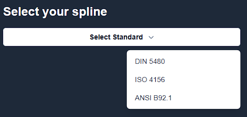
The first step is to select the spline standard you need to use. The standards are listed in the dropdown menu. The standards are as follows:
- DIN 5480 Spline Profile
- ISO 4156 Spline Profile
- ANSI B92.1 Spline Profile

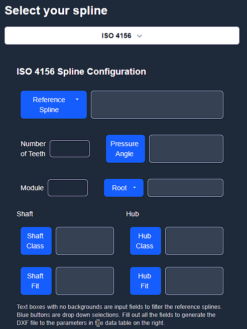
2. Fill out spline parameters and select a reference spline.
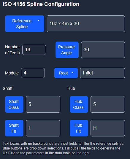
After selecting a spline standard, the next step is to fill out the spline parameters. They are split into two parts, the first part is the base parameters for the spline, Number of Teeth, Pitch/Module and root shape, and sometimes pressure angle or reference diameter. The second part is the fit of the spline, either an ISO fit or class fit. The spline will generate a nominal spline if a fit is not selected. The dxf will also not generate unless all the required parameters are filled out.

3. Select a reference spline.
After filling out the spline parameters, the next step is to select a reference spline. The reference splines are the base profiles used in manufacturing standards. They define the fundamental geometry and parameters for spline connections.

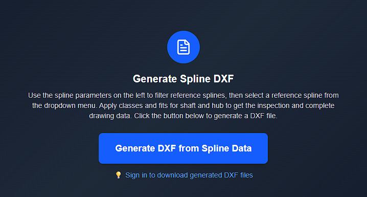
4. Generate the spline DXF
After filling out the spline parameters and selecting a reference spline click the generate dxf button to see the spline in the dxf viewer. The dxf viewer is a simple viewer that allows you to see the spline in the dxf format. The dxf viewer is not a full CAD software and does not allow you to edit the spline.

5. Download the spline DXF or try again
If the spline matches what you need, click the download dxf button to download the dxf file. If the spline does not match what you need you can hit new spline to try again.
